[toc]
利用vxlan构建二层虚拟机网络
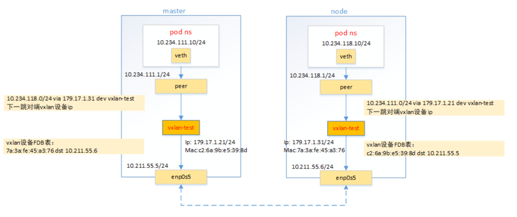
每台vm配置 vxlan 网卡以及 ip 地址且所有节点 vxlan 网卡的地址必须是同一个网段
| node name | node ip | vxlan-test ip | vxlan-test mac | pod network |
|---|---|---|---|---|
| master1 | 10.211.55.5 | 179.17.1.21 | c2:6a:9b:e5:39:8d | 10.234.111.0/24 |
| node1 | 10.211.55.6 | 179.17.1.31 | 7a:3a:fe:45:a3:76 | 10.234.118.0/24 |
方案
pod跨节点通信有flannel, calico等,通常采用vxlan,ipip等隧道技术。本文使用vxlan实现pod跨节点通信
整体步骤:
- 为所有节点创建 vxlan-test 虚拟网卡,并配置ip
- 在当前节点配置去往其他节点的 Pod 网段的路由信息且指定下一跳是目标节点的
vxlan-test网卡ip - 为每个节点的
vxlan-test网卡配置FDB和arp表,FDB表记录vxlan-test网卡的mac地址以及其节点的ip地址映射
创建vxlan设备及配置ip
1 | ip link add vxlan-test type vxlan id 10001 dstport 4899 local 10.211.55.5 dev enp0s5 nolearning |
1 | ip link add vxlan-test type vxlan id 10001 dstport 4899 local 10.211.55.6 dev enp0s5 nolearning |
配置ARP表和FDB表
使得所有节点的vxlan-test网卡之间可以互通。
on master1
1 | #配置ARP表, ip and mac of vxlan on other nodes |
on node1
1 | #配置ARP表, ip and mac of vxlan on other nodes |
创建pod netns
创建veth pair设备,连接ns和root ns
on master1
1 | // 创建ns, 并将一端放入ns中 |
on node
1 | ip netns add vxlan.ns1 |
1 | # ping 10.234.118.10 |
此时master无法感知到node上pod网络,所以不通
配置路由规则打通跨节点跨pod网络
on master
1 | route add -net 10.234.118.0/24 gw 179.17.1.31 dev vxlan-test |
on node
1 | route add -net 10.234.111.0/24 gw 179.17.1.21 dev vxlan-test |
测试
on master
1 | 在host上ping node pod ip |
on node
1 | # ping 10.234.111.10 |
1 | # ip netns exec vxlan.ns1 traceroute 10.234.118.10 |
ether pair -> peer node vxlan -> pod ip
看不到宿主机设备
vxlan是如何工作的
当pod出来的包,访问目的pod ip是10.234.118.10,作为内层包的dst ip, pod自己的ip就是内层包src ip, 根据节点上的路由规则
1 | 10.234.118.0/24 via 179.17.1.31 dev vxlan-test |
将会从本机的 vxlan-test 网卡出
vxlan-test设备进行封包
- 封装内层
mac, 该包下一跳是179.17.1.31,即peer node vxlan-test网卡的mac作为内层mac的dst mac。
peer node vxlan-test 网卡的mac可从master上的arp表会查询到。
疑问:如何拿到其他节点的vxlan mac,毕竟是任意设置的网络?
在本实验中是自己手动配置的
1 | # arp -n |
- 外层需要添加
vxlan header, 其中有vni标记,表明包由哪个vxlan设备处理,也就用作二层网络隔离。该vni标记是在创建vxlan设备时设置。 - 再加一层
udp header, udp的端口创建vxlan虚拟网卡时会设置。 - 然后封装外层包的
ip和mac层,通过内层dst mac查找vxlan-test网卡的FDB表, 找到peer node vxlan设备对应的宿主机ip, 且作为外层包dst ip,即设置为10.211.55.6(node宿主机的ip),src ip就是宿主机的ip1
2# bridge fdb show dev vxlan-test
7a:3a:fe:45:a3:76 dst 10.211.55.6 self permanent - 最外层的
mac根据master和node宿主机ip是否同网络而设置。如果不同网络,则是master网关网口的mac地址。本环境恰好是同网络,dst mac就是node宿主机的网口mac
6.vxlan包封装好后, 包经过master和node的宿主机网络最终到达node节点。node发现是一个vxlan包,内核将外层mac~udp剥掉后取出内部数据帧, 内核协议栈根据vxlan header中vni值交给vxlan-test处理,vxlan-test网卡拆包,比对dst mac是自己的,则剥掉mac取出原始的ip包(dst ip是pod ip),经过宿主机的路由达到目标pod中。
总结
- pod包会从
vxlan设备发且下一跳是peer node上的vxlan ip - 在本地arp表中,可获取
peer node vxlan设备的mac。 - 在本机fdb表里记录
peer node vxlan device mac和其所在节点的宿主机ip。 inner ip是两个pod的ipinner dst mac是peer node vxlan device mac.outer ip是宿主机的物理网口- 所有节点的
vxlan必须在同一个网络,大二层 - 节点可以有多个打二层,通过
vni区分